HOW TO WIRE UP AN ELECTRIC FAN.
A lot of people are now fitting electric fans to their kit cars, often because they have had to relocate the radiator away from the normal viscous fan.
There are a number of problems that arise, 1st, what do we use to switch the fan? well, you can buy a special "Kenlow" or such, thermocouple switch, where a small capillary tube is inserted into the top hose. These are fine, both adjustable and relatively easy to fit, the concern that I have with them is that they are a bit flimsy, and should you break it, or it go knackered, then you are into expense and a wait, due to it being a specialist part that will need ordering from one of the suppliers like Europa etc.
Recently, Stafford Vehicle Components have produced an aluminium "tube" that you fit into the top hose, these have a tapped boss welded onto them that will accept a sender switch from either the Ford Fiesta, or a Vauxhall. You just wire these into your fan, and you're away. I much prefer this method, as both the Ford & Vauxhall items are reliable, but easily obtained for a couple of pound, if that, from your local breaker.
OK, that's the switch, now the fan. I have personally used a couple of fans from the scrap yard, a Citroen BX is a "Pusher" and a Volvo 340,(I think) is a "puller" Both of these fans are very powerful, obviously there are other ones around and you may use something different, but whatever you use, expect to pay up to £10 for one from the scrapyard.
WIRING
A couple of problems that can occur with electric fans incorrectly wired are, the fan will come on whilst the water cools, even when the car is switched off, and with these powerful fans drawing a lot of current, I've seen cars that have stalled and be unable to be restarted if the fan is running, and only when it stops is there enough power to start the engine. This makes for red faces at traffic lights etc. should you be in this predicament.
We have found the best way to wire them up is as below, and it will work for any fan & switch combination. You need to make sure that you connect it to the correct terminal on the starter solenoid though!
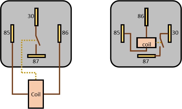
As a note of precaution, make sure that you use thick enough wire for the power & return cables to the fan, as they can draw around 30 amps. Also check which layout your relays are. There are generally two relay layouts and the wiring diagram assumes the first type below. Either way, check the terminal numbers on the relay itself - The coil is always across 85 and 86.

It is important that the "switching" wire from the relay, goes to the correct terminal at the starter, NOT the feed wire from the battery, but the small one from the solonoid to the field coils.
Technical description of the circuit (in case you are interested):
Basically, this circuit uses the very low impedance of the starter solenoid to provide a ground to the relay coil.
In normal operation, the +12 volts comes from the ignition switch to the thermostat. If the car is hot, the thermostat will switch on, sending that +12 volts to one side of the relay coil. That can then "escape" to ground through the starter solenoid coil to the chassis ground. The high resistance of the relay coil means that not enough current can flow to activate the starter solenoid.
When the ignition key is turned to the "engine start" position, the solenoid engages and supplies current to the starter motor. It also means that there is 12 volts on both sides of the relay coil, and therefore no voltage difference across it to activate the relay, and so the fan is switched off.